1-866-SDRobot (866-737-6268)


Wireless Serial Support Page
| USB Wireless Serial Interface Package | RS232 Wireless Serial Interface Package | OOPic SCP Visual Basic Interface Program |
Communicate with and program your micro-controller, wirelessly, using our RS232 or USB wireless system. The unit plugs into your PC via the USB or RS232 port and then transmits and receives data to and from your microcontroller. Our mobile transceiver board has two regulators (3.3V and 5V) to allow communications with either level TTL device. Status LEDs at both transceivers let you know the wireless link strength, status, and activity for Tx and Rx. We have set up the wireless transceiver board specifically to allow a quick and easy interface with your TTL microcontroller whether its 3V TTL or 5V TTL. It works great with the OOPic II Plus or OOPic-R.
- Description
- Mobile Transceiver Description and Use
- Schematic
- Hooking up to your PC
- Powering the Mobile Transceiver
- Hooking up the mobile Transceiver to TTL Rx and Tx
- Hooking up to an OOPic -R
- Hooking up to an OOPic II+
- Hooking up to an OOPic C
- Antenna Options for the Mobile Transceiver
- Mounting the Mobile Transceiver on your Trekker Robot
- Flashing the latest Firmware
- Updating xBee Parameters
- OOPic SCP Interface Program
Description:
The system operates on 2.4GHz and has multiple channels that can be used. We have used these with no issues/interference and we have wireless routers, phones, and cameras running at the same frequency. Indoors the unit gets better than 300 feet of reliable range, outdoors you can achieve up to 1 mile line of site. The system is FCC compliant and operates using the following:- ISM (industrial/ scientific/medical) 2.4 GHz operating frequency
- 60 mW (18 dBm), 100 mW EIRP power output (up to 1 mile range)
- Approved for use in the United States, Canada and Europe
The 2.4GHz ISM Wireless system replaces the physical serial cable by establishing a 'transparent' wireless link between your micro-controller/Serial Device and your wireless enabled PC/host device. So if you need to communicate with your mobile robot, remotely, our wireless system is an easily implemented solution.
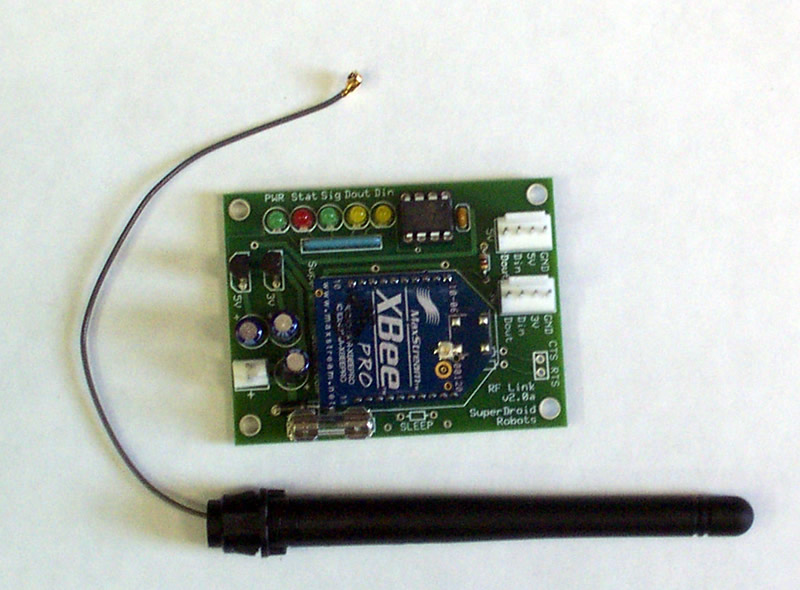
Mobile Transceiver Description and Use:

|
The LEDs on the board allow you to monitor all the Data going in and out through the XBee. The Signal LED will remain lit based on the signal strength of the last received package. If the single is getting week, the LED will turn off warning you that you are getting out of range. (BTW, with these XBee Pro Modules that is a long way 300+ feet indoors with many walls is not an issue, 1 mile line of site.)
The board measures about 5/8" high. However, with connectors and standoffs you should allow about an inch in height. The width is 1.9" by 2.5" long. When hooked up to 9.6V the current draw is about 115mA sending and transmitting data.
Click on the image for a larger more detailed view of the board.
Hookup Schematic:
Please review the sections below for additional details of hooking up your system. This is a general schematic for attaching a OOPic or any other TTL microcontroller or PIC to the mobile transceiver. You can view this as a PDF here.

|
Hooking up to your PC:
Plug the USB cable into an available USB port You should not need the power supply if your USB port has enough umph, otherwise use the supplied power supply. If using the RS232 package use a serial cable and plug in the power supply. Follow the instructions provided with the xBee PRO package. For the USB package drivers will need to be installed on your computer. The drivers are included on the MaxStream CD. You can get support from www.maxstream.net.Powering the Mobile Transceiver:
The Mobile Transceiver needs 7 to 18 VDC supplied on the 2 pin power header.  If you are using a OOPic or Trekker Expansion board see the descriptions below for hooking up the power. The header pins are supplied with the wireless serial kits. For crimping see this link.Hooking up the mobile Transceiver to TTL Rx and Tx:
The Din and Dout Pins need to be hooked up to the TTL Rx and Tx. If you have a microcontroller that has 5V logic, hook up to the 5V serial header, if you have 3.3V logic, hook up to the 3V serial header. Do not power the mobile transceiver from the serial headers. You can power your microcontroller from the serial header, but only if its very low current draw (<100ma). Typically you should not hook up the +5 or +3 pin on the serial header. If you are hooking up to a device that requires RS232 levels, you can attach any of our type 1 cables to the serial header and the cable will get its power from the mobile transceiver. The header pins are supplied with the wireless serial kits. The mobile transceiver and the microcontroller need to share a ground too, you can do this through the serial header or by using a common battery.As a test of the system, you can couple the Din and Dout pins then using X-CTU perform a range test. During this X-CTU will transmit data and the mobile transceiver will send it back for a loop back test.
Hooking up to an OOPic-R:
 You can plug into the OOPic-R on the TTL connections as shown in adjacent image. You will need to access the OOPic-R TTL outputs, which on the underside of the board. You will need to solder two pieces of wire and connect to the Din and Dout ports on the 5VTTL header on the Mobile Transceiver board. In the figure, ground is not attached to the TTL header on the Mobile Transceiver board, which is fine provided you are using the same power supply, hence the common ground is via the power. If using different power sources, you will need to connect the Mobile Transceiver board ground and the OOPic ground together for proper operation. Wire, crimps, and connectors are provided to allow you to make this connection.
If you do not wish to make the two solder connections on the OOPic, you can plug into the OOPic-R DB9 with one of our Type 1 RS232 converter cables to the TTL header. A null modem cable will be required between the OOPic-R DB9 connector and the converter cable to swap pin 2 and 3.
 If you are using a Trekker OOPic-R Expansion board you can grab power for the OOPic-R power header, which will not be energized until you turn on the Expansion board switch. Refer to the adjacent figure. If you do not have the expansion board, you can grab power from the +MP and GND pins right next to the OOPic-R Power Header. All the necessary headers, crimp pins, etc are provided to allow you to make one of these connections.
Hooking up to an OOPic II+
You can hook up to the OOPic II+ Expansion board or directly to the OOPIc II+. The OOPic II+ allows SCP and programming via the serial port. There are a lot of possible ways to connect the OOPic to the Mobile Transceiver. Hooking up the Expansion board can be done as shown in the adjacent figure. You need to make the power cable to the Mobile Transceiver and attach it the the power outputs on the expansion board as shown. The serial is passed from the 4 pin serial headers as shown. The Tx and Rx of the Expansion Board needs to go the the Rx and Tx of the Mobile Transceiver respectively. You do not need to hook up the ground wire if you do not want to for the TTL if you are sharing a common ground for power. Wire, crimps, and connectors are provided to allow you to make this connection.
If you do not have an expansion board, you can solder the provided 4 pin header on the OOPic as shown for your serial connection. In both cases you want to plug into the 5V TTL header on the the Mobile Transceiver.
 |
Attaching the supplied 4 pin header to your OOPic II+ Board:
|

Hooking up to an OOPic-C:
You can plug into the OOPic-C. You will want to connect the Tx and Rx pins that are brought out to the through holes on the OOPic. Hooking up here will allow you access the TTL lines. See the OOPic-C schematic. You do not want to connect to the pins 1 an 2 of the OOPic-C since these have level shifting on them. You will need to solder two pieces of wire and connect to the Din and Dout ports on the 5VTTL header on the Mobile Transceiver board. The ground must be common between the OOPic and the mobile Transceiver. If using different power sources, you will need to connect the Mobile Transceiver board ground and the OOPic ground together for proper operation.ÂAntenna Options for the Mobile Transceiver
There are two styles of antenna you can choose from. The wire antenna is just a short (~1" piece of wire soldered to the XBee). This is the best all around choice since its very compact and still offers great range. As an alternative you can get a pigtail antenna that is a simple dipole antenna that has a ~6" wire that snaps onto the XBee. This is a good choice if the Mobile Transceiver is going to be mounted inside your robot and you need to get the antenna outside of the robot.

|
|
| wire antenna (click for larger view) | pigtail antenna (click for larger view) |
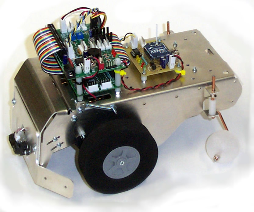
Mounting the Mobile Transceiver on your Trekker Robot
The Mobile Transceiver comes with mounting hardware and nylon standoff spacers. The boards holes are lined up to match the Trekker battery tray bolts. Just remove the short battery tray machine screws and replace them with the provided screws, put nylon spacers under the board. The other two holes we just make legs to rest on the Trekker. Refer to the figures below. |
 |
Flashing the latest Firmware:
The xBee may not come with the latest firmware installed on it. In order for it to perform optimally, especially when streaming data such as programming your compiler, the latest firmware should be flashed to the xBee. You must flash the xBee when directly coupled to a PC. To flash the xBee on the mobile transceiver, you must remove the xBee module and install it on the USB or RS232 module. If you open the two RS232 or USB module housing by removing one of the side panels (the side with the antenna is a little easier) you can slide the whole board out, remove the xBee module on the board and put the xBee that was in the mobile transceiver in the socket. You will need to flash both xBee modules with the same firmware. When the xBee is connected to your PC via the RS232 or USB port perform the following:- Connect an XBee RF Module to an XBIB-R or -U interface board, connect to the serial port of a PC, and power it on.
- Ensure you have the latest version of X-CTU, available at http://www.maxstream.net/helpdesk/download.php.
- Open X-CTU and select the "MaxStream PKG" com port
- Set ‘PC Settings’ tab to: 9600 baud, Hardware flow control, 8, NONE, 1.
- Under the ‘Modem Configuration’ tab click the ‘Download new versions…’ button, select ‘Web’. X-CTU will download all available updates.
- Click ‘Open,’ ‘OK,’ then ‘Done.’
- X-CTU should now have the new firmware files in memory. However the XBee modem still needs to be flashed with the new firmware.
- Under the ‘Modem Configuration’ tab choose ‘XBP24’ from the ‘Modem:’ pull-down menu.
- Choose ‘XBEE PRO 802.15.4’ from the ‘Function Set:’ pull-down menu.
- Choose ‘1083’ from the ‘Version:’ pull-down menu. (later versions may be available)
- Click ‘Write’ to flash the XBee modem with the v107E firmware.
- This same procedure needs to be performed for both transceivers. The Mobile transceiver can not be flashed wirelessly, you may attach a type 1 serial coverter cable to the serial port, or you can carefully remove the transceiver from the mobile transceiver board and swap it with the one inside the wireless modem (inside the black box). Make sure the boards are powered down when you swap them. You then just repeat the steps above (except you don't need to download the latest versions of firmware).
Updating xBee Parameters:
There are many settings you can change on the xBee such as channel selection, baud rate (default is 9600), etc. You must flash the xBee when directly coupled to a PC. You will need to flash both xBee modules with the same updates. You would use this same method to of swapping the cards to change the parameters such as channels, etc. as described above, or you can change the parameters while the xBee is on the mobile transceiver by plugging in one of our Type 1 RS232 converter cables to the TTL header.OOPic SCP Interface Program
 |
One of the neatest features of the wireless interface is you can control the OOPic with SCP (Serial Control Protocol). We have developed a program to help you do this. The program has many features. Click on the image for a screen shot of some of the functions. The program comes with its own help file, which you can download to see what's involved with the program. |
