SuperDroid Robots
Tactical Robots
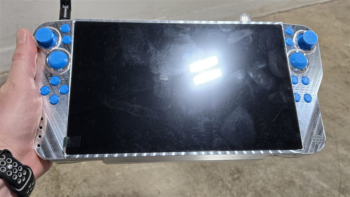
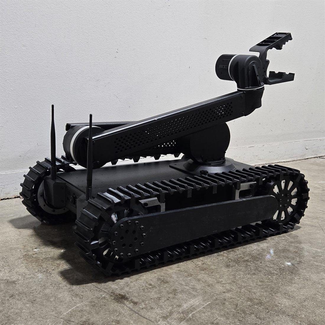
Tactical robots of every size and for any budget, designed and built for surveillance, investigation, and negotiation. From the compact Jack Russell to the multi-purpose Bulldog and heavy-duty Mastiff, our Unmanned Ground Vehicles (UGVs) let your team assess dangerous situations from a safe distance.
Every robot is customizable — or we can build from scratch. We design, build, test, and support all of our robots at our facility in North Carolina, USA.
Explore tactical droids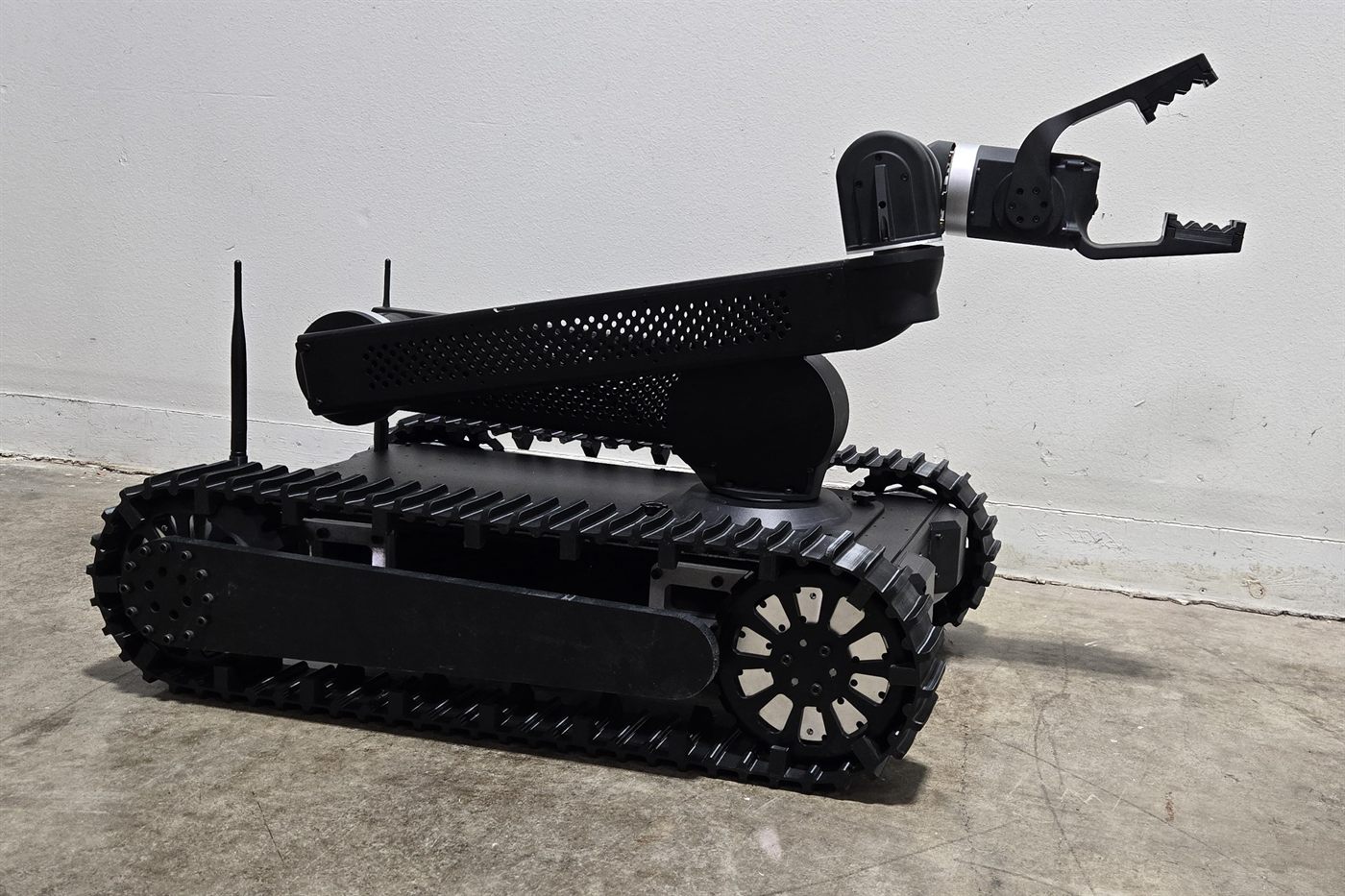
Bulldog