1-866-SDRobot (866-737-6268)


Motor Wiring Support
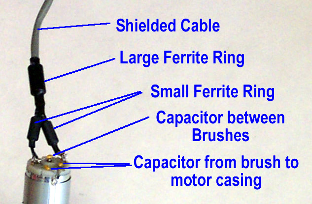
When using electric motors, one of the most important things to consider is motor noise. We sell several DC motors for our ATR and Vectoring Robot kits. With these motors we recommend you get a motor wiring kit too. The motor wiring kit provides protection and helps knock down the majority of the noise the motors put out. There are a lot of schools of thought on how to control the noise, below is what we have found is the best practice for noise suppression.- Step 1: Take two capacitors and twist them together.
- Step 2: Scratch a spot on the motor between the two terminals as shown. Using soldering iron apply some solder. Then solder the twisted end of the two capacitors to the spot on the motor case as shown.
- Step 3: Take the other end of the twisted pair of capacitors and insert one end to each motor brush terminal.
- Step 4: Place a third capacitor between each motor brush terminal.
- Step 5: Strip back the shielded wire leaving the two conductors about 2-3" out.
- Step 6: Slide the large ferrite ring over the shielded wire and cover it with the 3/8" heat shrink.
- Step 7: Insert the small ferrite rings into the 1/4" heat shrink (this is a real tight fit) and then slide over each wire conductor.
- Step 8: Place the wires on the motor brush terminals. You want to be consistent with which color wire goes to which terminal so all your motors are wired and hooked up the same. We place the white wire on the terminal with a red dot. You may need to use a high power soldering gun or torch to heat up the motor casing and ensure you get good adhesion.
- Step 9: Solder the wires and the capacitors to each motor terminal being careful not to overheat any of the components.
- Step 10: Heat the shrink wrap on the wires securing the ferrite rings.
|
