1-866-SDRobot (866-737-6268)


SRF04 Ultrasonic Sensor Support
| SRF04 Ultrasonic Scanner | Trekker Ultrasonic Scanner Kit | Trekker Sweeping Ultrasonic Scanner Kit | All Sensors | SRF08 Ultrasonic Sensors |
Devantech SRF04 Ultrasonic Ranger
 |
 |
This high performance ultrasonic range finder is compact and measures an amazingly wide range from 3cm to 3m. This ranger is a perfect for your robot or any other projects requiring accurate ranging information.
Specifications
Beam Pattern |
see below |
| Voltage | 5v |
| Current | 30mA Typ. 50mA Max |
| Frequency | 40KHz |
| Maximum Range | 3 m |
| Minimum Range | 3 cm |
| Sensitivity | Detect a 3cm diameter stick at > 2 m |
| Input Trigger | 10uS Min. TTL level pulse |
| Echo Pulse | Positive TTL level signal, width proportional to range. |
| Weight | 0.4 oz. |
| Size | 1.75" w x 0.625" h x 0.5" d |
Specifications subject to change without notice
Beam Pattern
 |
Theory of Operation
The ranger works by transmitting a pulse of sound outside the range of human hearing. This pulse travels at the speed of sound (roughly 0.9 ft/msec) away from the ranger in a cone shape and the sound reflects back to the ranger from any object in the path of this sonic wave. The ranger pauses for a brief interval after the sound is transmitted and then awaits the reflected sound in the form of an echo. The controller driving the ranger then requests a ping, the ranger creates the sound pulse, and waits for the return echo. If received, the ranger reports this echo to the controller and the controller can then compute the distance to the object based on the elapsed time.Connections
| We have many programs using the OOPic with the SRF04 with the Trekker. Also, Devantech has examples using the SRF04 module with a wide range of popular controllers. Want to know the history of this little module, and even more information? |
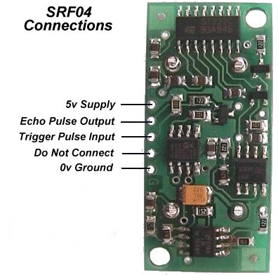 |
The ranger requires four connections to operate. First are the power and ground lines. The ranger requires a 5V power supply capable of handling roughly 5OmA of continuous output. The remaining two wires are the signal wires.
The connections can be made by soldering wire leads to the board or header pins/sockets.
Basic Timing
There are a couple of requirements for the input trigger and output pulse generated by the ranger. The input line should be held low (logic 0) and then brought high for a minimum of 10usec to initiate the sonic pulse. The pulse is generated on the falling edge of this input trigger. The ranger's receive circuitry is held in a short blanking interval of 100usec to avoid noise from the initial ping and then it is enabled to listen for the echo. The echo line is low until the receive circuitry is enabled. Once the receive circuitry is enabled, the falling edge of the echo line signals either an echo detection or the timeout (if no object echo is detected).Your controller will want to begin timing the falling edge of your trigger input and end timing on the falling edge of the echo line. This duration determines the distance to the first object the echo is received from.
 Click on image for larger/clearer view |
Interface Example
This example demonstrates the SRFO4 interface to a Basic Stamp II. Interfacing with the OOPic is a lot easier!For an OOPic example follow this link. This example uses the Basic Stamp II carrier board and debug output capability to take continuous readings from the SRFO4 and display them in the debug console of the Stamp development environment. |
Example; Code:
'Devantec SRFO4/Basic Stamp II Example- wDist var word
- INIT con 1
- ' The PULSIN command returns the round-trip
- 'echo time in 2us units which is equivalent to
- ' the one-way trip time in 1 us units
- ' distance = (echo time)/ conversion factor)
- ' use 74 for inches
- ' use 29 for centimeters
main
- gosub sr_sonar
- debug dec wDist,cr
- pause 200
- go to main
sr_sonar:
- pulsout INIT, 5 '10us pulse
- pulsin ECHO,l,wDist wDist 'measure echo time
- wDist/convfac 'convert to inches
- pause 10
sr_sonar_2:
- pulsout INIT, 5 '10us init pulse
- output INT 'dummy command (delay)
- rctime ECHO,l,wDist 'measure echo time
- wDist = wDist/convfac 'convert to inches
- pause 10
- return
