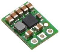

This current sensor is a carrier board or breakout board for Allegro’s
ACS714LLCTR-30A-T Hall effect-based linear current sensor; we therefore
recommend careful reading of the
ACS714
datasheet (661k pdf) before using this product. The sensor operates
at 5 V and has an output sensitivity of 66 mV/A. The board ships fully
populated with its SMD components, including the ACS714, as shown in the
product picture. The following list details some of the sensor’s key
features:
- Designed for bidirectional input current from -30 to 30 A (though the
robust sensor IC can survive up to five times the overcurrent
condition).
- Conductive path internal resistance is typically 1.2 mΩ, and the PCB
is made with 2-oz copper, so very little power is lost in the board.
- Use of a Hall effect sensor means the IC is able to electrically
isolate the current path from the sensor’s electronics (up to 2.1 kV
RMS), which allows the sensor to be inserted anywhere along the current
path and to be used in applications that require electrical isolation.
- 80 kHz bandwith that can optionally be decreased by adding a capacitor
across the board pins marked “filter”.
- High accuracy and reliability: typical total output error of ±1.5% at
room temperature with factory calibration, an extremely stable output
offset voltage, and almost zero magnetic hysteresis.
- Automotive-grade operating temperature range of -40°C to 150°C.
The pads are labeled on the bottom silkscreen, as shown in the picture to
the right. The silkscreen also shows the direction that is interpreted as
positive current flow via the +i arrow.
We sell a
30A unidirectional version
and ±5A bidirectional version version
of this board; you can distinguish these versions by reading the text on
the IC or by looking at the color of the X on the bottom silkscreen. This
version is marked with a red X.
Electrical connections
 |
| ACS715 current sensor carrier with solderless ring terminal connectors (not included). |
The sensor requires a supply voltage of 4.5 – 5.5 V to be connected
across the Vcc and GND pads, which are labeled on the bottom silkscreen.
The sensor outputs an analog voltage that is linearly proportional to the
input current. When Vcc is 5 V, this output voltage is centered at 2.5 V
and changes by 66 mV per amp of input current, with positive current
increasing the output voltage and negative current decreasing the output
voltage.
The input current can be connected to the board in a variety of ways. For
low-current applications, you can solder 0.1"
male header pins to the board via the small through-holes on the
input-current side of the board. For higher-current applications, you can
solder wires directly to the through-holes whose sizes best match your
wires, or you can use solderless ring terminal connectors, as shown in the
picture to the right. The large through-holes are big enough for #6
screws.
Mounting information
The board has two mounting holes on the logic side of the board. These
mounting holes are 0.5" apart and are designed for #2 screws.
Filtering the output
The IC has an internal filter resistance of 1.7 kΩ, and the carrier board
includes a 1 nF filter capacitor, which produces a low-pass RC filter with
a 90 kHz cutoff. You can improve sensing system accuracy for low-frequency
sensing applictations by adding a capacitor in parallel with the
integrated 1 nF capacitor across the pads marked “filter” on the bottom
silkscreen (this capacitor is labeled C2b in the schematic below). The
frequency F that the filter will attenuate to half its original
power is given by:
F = 1 / (2πRC) = 1 / (11kΩ * (1 nF + Cf))
where Cf is the value of the capacitor added to the filter pads.
 |
| ACS714/ACS715 current sensor carrier schematic diagram. |
Dimensions
| Size: |
0.7" x 0.8" |
| Weight: |
1.3 g |
General specifications
| Current sense: |
0.066 V/A (see note 1) |
| Minimum logic voltage: |
4.5 V |
| Maximum logic voltage: |
5.5 V |
| Supply current: |
13 mA |
Notes:
- When Vcc is 5 V.
File downloads