@jason
active 2 months, 3 weeks ago-

Jason Traud replied to the topic motors behaviours in the forum Electrical & Controls 4 months, 2 weeks ago
It sounds like your settings in RoboRun aren’t quite correct. Roboteq’s support forum will be able to help you better with that. The settings will be located on the Configuration tab.
I would also make sure that the appropriate inputs are toggling on the Run tab. This will verify that you are making the proper connections.…[Read more]
-
Jason Traud replied to the topic Wifi ATR software issue in the forum Electrical & Controls 5 months ago
Please send us an email with an order number so I can pull up the specific configuration and firmware for your control package.
-
Jason Traud replied to the topic Wifi ATR software issue in the forum Electrical & Controls 5 months ago
Double check the network protocol. Most of the control systems we produce are configured for TCP due to port forwarding. Also try setting a static IP address on your computer to the appropriate subnet. You can also try connecting directly to your system or through a switch to rule out the possibility of an odd networking issue with your…[Read more]
-
Jason Traud replied to the topic Wifi ATR software issue in the forum Electrical & Controls 5 months ago
Have you loaded the appropriate settings file for your robot?
-
Jason Traud started the topic Tech Thursday 020: Motor Controller Selection and SIzing in the forum Tutorials and Blog Specific 5 months ago
A common question we get asked is “What motor controller should I use?”. There are two main criteria you need to look at: communication protocols and current capacity. The first isn’t a big issue with modern motor controllers since most have such a wide range of inputs spanning analog control, R/C, to serial. However, it’s worth noting that it…
-
Jason Traud started the topic Tech Thursday 020: Motor Controller Selection and SIzing in the forum Tutorials and Blog Specific 5 months ago
A common question we get ask is “What motor controller should I use?”. There are two main criteria you need to look at: communication protocols and current capacity. The first isn’t a big issue with modern motor controllers since most have such a wide range of inputs spanning analog control, R/C, to serial. However, it’s worth noting that it…
-
Jason Traud started the topic Tech Thursday 020: Motor Controller Section and SIzing in the forum Tutorials and Blog Specific 5 months ago
A common question we get ask is “What motor controller should I use?”. There are two main criteria you need to look at: communication protocols and current capacity. The first isn’t a big issue with modern motor controllers since most have such a wide range of inputs spanning analog control, R/C, to serial. However, it’s worth noting that it…
-
Jason Traud replied to the topic Using a DX3 in the forum Electrical & Controls 5 months ago
With a DX3 you have three signals; the trigger (throttle), the wheel (steer), and an auxiliary input. Connectng the throttle on your receiver to S1 and Steer to S2 you will be able to drive and turn your robot with the DX3.
From the sound of your setup, you will need to configure the motor controller by setting the DIP switch to 01 11 11 (0…[Read more]
-
Jason Traud replied to the topic Kangaroo 2X motion controller in the forum Product Questions 5 months ago
That is correct. I would suggest powering the combined Sabertooth+Kangaroo with your drive battery. I find it makes tuning it in Describe a little bit easier.
-
Jason Traud replied to the topic Kangaroo 2X motion controller in the forum Product Questions 5 months, 1 week ago
That should work just fine. Be sure that the motor controller is set to packetized serial mode with an address of 128. Dip setting 00 11 11.
Also be sure that your DELink is connected properly. Tx on the DELink should be connected to S1 on the Kangaroo, Rx should be connected to S2. Be sure that you have a ground connected but not power. When…[Read more]
-
Jason Traud replied to the topic Doubling Motor Controller Channels? in the forum Electrical & Controls 5 months, 1 week ago
Daniel,
You should have no issue doing that.
-
Jason Traud replied to the topic motors problem in the forum Product Questions 5 months, 1 week ago
I would keep them controlled connected in parallel. You may want to consider coupling the sides with a chain to ensure that they spin at the same speed. At that point you will only need to monitor one encoder on both sides.
-
Jason Traud replied to the topic motors problem in the forum Product Questions 5 months, 1 week ago
Yes. No two motors are exactly alike. There are variances in manufacturing and then you will have variances in motor wiring and then you’ll also have variances in the load on the motors.
This is why speed control is important and you will need to make use of the feedback from the encoders to adjust the power being sent to the motors.
-
Jason Traud replied to the topic encoder in the forum Electrical & Controls 5 months, 3 weeks ago
If you’re only getting pulse changes when you physically move the encoder board then it sounds like it’s a wiring or solder issue.
How do you have the wires connected to the RoboteQ’s DB15? If you just have wires stabbed into it and not using a crimp or solder-cup connector then you most likely do not have a solid electrical connection.
When…[Read more]
-
Jason Traud replied to the topic encoder in the forum Electrical & Controls 5 months, 3 weeks ago
If you’re only getting pulse changes when you physically move the encoder buffer then it sounds like it’s a wireing or solder issue.
How do you have the wires connected to the RoboteQ’s DB15? If you just have wires stabbed into it and not using a crimp or solder-cup connector then you most likely do not have a solid electrical connection.
When…[Read more]
-
Jason Traud replied to the topic encoder in the forum Electrical & Controls 5 months, 3 weeks ago
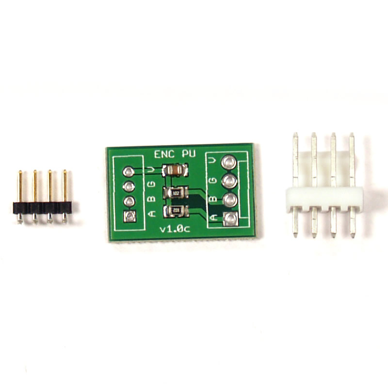
As seen in the datasheet below there are six total wires/terminals on the motors.
1. Black - Motor Power Negative
2. Red - Motor Power Positive3. Brown - Hall Sensor Power
4. Green - Hall Sensor Ground
5. Blue - Hall Sensor - A Channel
6. Purple - Hall Sensor - B ChannelThe Encoder Pull-Up board has two connectors on each side. The smaller header has a 2.0mm pitch and will mate directly with the encoder connector on the motor. Be sure to match up the pins properly. The pin marked V is encoder power, G is encoder ground, B is B channel and A is A channel. The opposite side needs to be wired into the DB15 connector on your RoboteQ motor controller.
To determine the connections on the RoboteQ you will need to refer to their datasheet. According to the datasheet below you will need to connect the “V” pin on the Encoder Pull-Up board to pin 14 (which is 5V Output). The “G” pin needs to be connected to either pin 5 or 13 (Ground). You will need to be sure you match up your encoder pulses to the proper channel. The motor connected to the M1 output terminals will need to be connected to pins 4 and 8 on the RoboteQ’s DB15 connector. The motor connected to M2 needs to be connected to pins 10 and 15 on the DB15 connector.
-
Jason Traud replied to the topic encoder in the forum Electrical & Controls 5 months, 3 weeks ago
The suggested wiring schematic can be found on page 4 of the datasheet below. The motor controller itself needs to be powered by your 24V drive batteries. This is connected directly to the VMot and Gnd terminals on your motor controller.
Your motors are connected to M1+, M1-, M2+, and M2-. Be sure that the terminals marked M1 go to one motor and…[Read more]
-
Jason Traud replied to the topic WiFi ATR Software Crashing on Boot in the forum Electrical & Controls 5 months, 3 weeks ago
This issue was resolved over email. One of the .NET dependencies was not installed.
- Load More