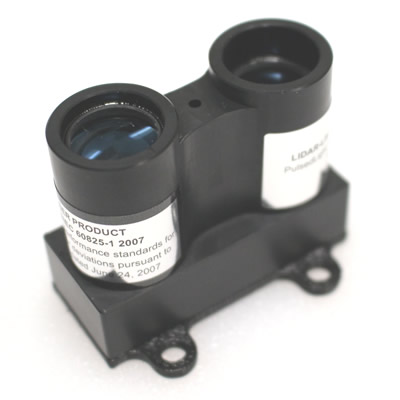
PulsedLight’s LiDAR-Lite (TS-070-001) is a compact and high performance distance measurement sensor. The small size and light weight makes it an ideal positioning sensor in mobile robotic applications. The sensor also boasts an incredibly wide operating range. It can accurately measure from about 5cm all the way up to 40 meters! This makes the sensor great for both precision and distance measurement.
How does it work?
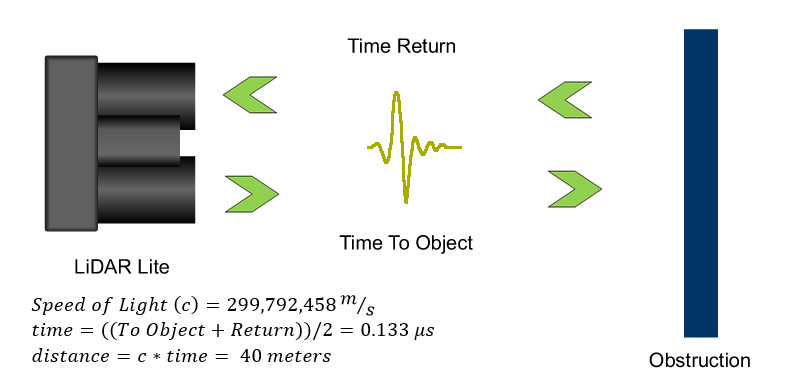
Optical distance measuring solutions operate on the principle of “Time-of-Flight” (ToF). The total distance to the object is calculated by the amount of time it takes the sensor’s “chirp” to bounce off of a target and be reflected back to the sensor. In this case it will be a burst of IR light from the emitter diode on the sensor.
Specifications
| Signal/Power Interfaces | Specifications |
|---|---|
| Power | 4.7 - 5.5VDC Nominal |
| Weight | 16 grams with optics, housing, and PCB |
| Size | 21 x 48.6 x 35.5 mm housing |
| Current Consumption | < 100ma continuous operation |
| Max Operating Temp. | 70 degrees C |
| External Trigger | 3.3V logic, high-low edge triggered |
| PWM Range Output | PWM Signal proportional to range, 1msec/meter |
| I2C Machine Interface | 100Kb - Fixed, 0xc4 slave address |
| Supported I2C Commands | Single Distance Measurement, Velocity, Signal Strength |
| Mode Control | Busy status Using I2C |
| System Parameters | |
|---|---|
| Max Range @1 Hz, 30% Target | 30 Meters |
| Max Range @1Hz, 90% Target | 60 Meters |
| Accuracy | +/- 0.025 meter |
| Acquisition Time | < 0.02 sec |
| Max Rep Rate | 100 Hz |
Applications
The primary uses for a LiDAR sensor are object detection, collision avoidance, edge detection, positioning, and mapping. For basic collision detection the sensor can be mounted flush to the outside of your robot, or at a slight angle to be able to detect objects in your path. When mounted at a more extreme angle the sensor can be used for edge detection, meaning it’ll sense when it’s approaching stairs or a cliff. As a positioning sensor, when attached to a pivot point of a stepper motor or servo the sensor’s long range allows it to find and track points around itself. This data can be used to build up a 3D map of an area or to determine the robot’s position based on how far it is away from known points of a room.
Implementing the Sensor
There are two operating modes for the sensor: PWM output and I2C. To set the sensor to PWM output you must pull pin three high. Otherwise, a floating or grounded state will put us in I2C mode. To use the LiDAR in I2C mode, refer to the code below.
|
1 2 3 4 5 6 7 8 9 10 11 12 13 14 15 16 17 18 19 20 21 22 23 24 25 26 27 28 29 30 31 32 33 34 35 36 37 38 39 40 41 42 43 44 45 |
/* http://pulsedlight3d.com This sketch demonstrates getting distance with the LIDAR-Lite Sensor It utilizes the 'Arduino Wire Library' */ #include <Wire.h> #define LIDARLite_ADDRESS 0x62 // Default I2C Address of LIDAR-Lite. #define RegisterMeasure 0x00 // Register to write to initiate ranging. #define MeasureValue 0x04 // Value to initiate ranging. #define RegisterHighLowB 0x8f // Register to get both High and Low bytes in 1 call. int reading = 0; void setup() { Wire.begin(); // join i2c bus Serial.begin(9600); // start serial communication at 9600bps } void loop() { Wire.beginTransmission((int)LIDARLite_ADDRESS); // transmit to LIDAR-Lite Wire.write((int)RegisterMeasure); // sets register pointer to (0x00) Wire.write((int)MeasureValue); // sets register pointer to (0x00) Wire.endTransmission(); // stop transmitting delay(20); // Wait 20ms for transmit Wire.beginTransmission((int)LIDARLite_ADDRESS); // transmit to LIDAR-Lite Wire.write((int)RegisterHighLowB); // sets register pointer to (0x8f) Wire.endTransmission(); // stop transmitting delay(20); // Wait 20ms for transmit Wire.requestFrom((int)LIDARLite_ADDRESS, 2); // request 2 bytes from LIDAR-Lite if(2 <= Wire.available()) // if two bytes were received { reading = Wire.read(); // receive high byte (overwrites previous reading) reading = reading << 8; // shift high byte to be high 8 bits reading |= Wire.read(); // receive low byte as lower 8 bits Serial.println(reading); // print the reading } } |
Practical Tests
We’ve been able to put this LiDAR through some paces. We were interested in how the sensor would perform when placed behind clear plastic such as a protective sheet of Lexan or one of our 6-inch plastic dome covers (WC-021-000). Going through a clean sheet did not affect the readings. We’ve also tested the sensor on how it would handle more extreme angles for the application of obstacle and edge detection. The sensor proved reliable past a 45 degree sensing angle.
Documentation and Support