Pololu MinIMU-9 Gyro, Accelerometer and Compass - DISCONTINUED
Specifications
- Dimensions: 0.9" x 0.6" x 0.1" (23 x 15 x 3 mm)
- Weight without header pins: 0.9 g (0.03 oz)
- Operating voltage: 2.6 to 5.5 V
- Supply current: 10 mA
- Output format (I²C):
- Gyro: one 16-bit reading per axis
- Accelerometer: one 12-bit reading (left-justified) per axis
- Magnetometer: one 12-bit reading (right-justified) per axis
- Sensitivity range (configurable):
- Gyro: ±250, ±500, or ±2000°/s
- Accelerometer: ±2, ±4, or ±8 g
- Magnetometer: ±1.3, ±1.9, ±2.5, ±4.0, ±4.7, ±5.6, or ±8.1 gauss
Included Components
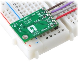
A 6 x 1 strip of 0.1" header pins and a 6 x 1 strip of 0.1" right-angle header pins are included, as shown in the picture below. You can solder the header strip of your choice to the board for use with custom cables or solderless breadboards, or you can solder wires directly to the board itself for more compact installations.
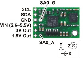
Connections
A minimum of four connections are necessary to use the MinIMU-9: VIN, GND, SCL, and SDA. VIN should be connected to a 2.6 - 5.5 V source, GND to 0 volts, and SCL and SDA should be connected to an I²C bus operating at the same logic level as VIN.
|
|
Schematic Diagram
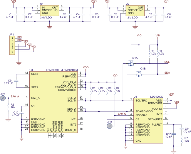 |
The above schematic shows the additional components the carrier board incorporates to make the L3G4200D and LSM303 easier to use, including the voltage regulators that allow the board to be powered from a single 2.6 - 5.5 V supply and the level-shifter circuit that allows for I²C communication at the same logic voltage level as VIN. This schematic is also available as a downloadable pdf: MinIMU-9 schematic (36k pdf).
I²C Communication
The L3G4200D and LSM303DLM readings can be queried and the devices can be configured through the I²C bus. The three sensors (the L3G4200D gyro and the LSM303DLM accelerometer and magnetometer) act as slave devices on the same I²C bus (i.e. their clock and data lines are tied together to ease communication). Additionally, level shifters on the I²C clock (SCL) and data lines (SDA) enable I²C communication with microcontrollers operating at the same voltage as VIN (2.6 - 5.5V). A detailed explanation of the protocols used by each device can be found in the L3G4200D datasheet (1MB pdf) and the LSM303DLM datasheet (519k pdf), and more detailed information about I²C in general can be found in NXP's I²C-bus specification (371k pdf).
The gyro, accelerometer, and magnetometer each have separate slave addresses on the I²C bus. The gyro and accelerometer's 7-bit slave addresses have their least significant bit (LSb) determined by the voltage on the SA0_G and SA0_A pins, respectively. The carrier board pulls SA0_G to 1.8 V and SA0_A to ground through 4.7kO resistors, setting the gyro's slave address to 1101001b and the accelerometer's slave address to 0011000b by default. If the gyro's selected slave address happens to conflict with some other device on your I²C bus, you can drive SA0_G low to set the LSb to 0; similarly, you can drive SA0_A high (by connecting it to 1.8 V) to set the LSb of the accelerometer's slave address to 1. The magnetometer's slave address is 0011110b and cannot be changed.
In our tests of the MinIMU-9, we were able to communicate with both chips at clock frequencies up to 400 kHz; higher frequencies might work but were not tested. The chips themselves and carrier board do not meet of some requirements to make the devices compliant with I²C fast mode. They are missing 50 ns spike suppression on the clock and data lines, and additional pull-ups on the clock and data lines might also be necessary to achieve compliant signal timing characteristics.
Sample Code
We have written a basic L3G4200D Arduino library and LSM303 Arduino library that make it easy to interface the MinIMU-9 with an Arduino. The libraries make it simple to configure the sensors and read their raw gyro, accelerometer, and magnetometer data.
For a demonstration of what you can do with this data, you can turn an Arduino connected to a MinIMU-9 into an attitude and heading reference system, or AHRS, with this Arduino program. It uses the data from the MinIMU-9 to calculate estimated roll, pitch, and yaw angles, and you can visualize the output of the AHRS with a 3D test program on your PC (as shown in a screenshot above). This software is based on the work of Jordi Munoz, William Premerlani, Jose Julio, and Doug Weibel.
Protocol Hints
The datasheets provide all the information you need to use the sensors on the MinIMU-9, but picking out the important details can take some time. Here are some pointers for communicating with and configuring the L3G4200D and LSM303DLM that we hope will get you up and running a little bit faster:
- The gyro, accelerometer, and magnetometer are all off by default. You have to turn them on by setting the correct configuration registers.
- You can read or write multiple gyro or accelerometer registers in a single I²C command by asserting the most significant bit of the register address to enable address auto-increment.
- The magnetometer will not update its data until all 6 data bytes have been read during a single I²C transfer. All the bytes can be read in the same transfer using the the magnetometer's automatic sub-address updating feature (this feature is enabled by default).
- The LSM303DLM combines an accelerometer and a magnetometer made by separate manufacturers into one IC, so there are fairly significant differences in their features, functionality, and interfaces. The interface of the L3G4200D is similar to that of the accelerometer in the LSM303DLM.
Dimensions
- Size: 0.9" x 0.6" x 0.1" (see Notes below)
- Weight: 0.9 g (see Notes below)
General specifications
- Interface: I²C
- Minimum operating voltage: 2.6 V
- Maximum operating voltage: 5.5 V
- Axes: pitch (x), roll (y), and yaw (z)
- Measurement range: ±250, ±500, or ±2000°/s (gyro)
±2, ±4, or ±8 g (accelerometer)
±1.3, ±1.9, ±2.5, ±4.0, ±4.7, ±5.6, or ±8.1 gauss (magnetometer) - Supply current: 10 mA
Notes
- Without included hardware.
Documentation
- MinIMU-9 schematic diagram (36k pdf)
- L3G4200D datasheet (1MB pdf). Datasheet for the ST L3G4200D ultra-stable three-axis digital-output gyroscope.
- LSM303DLM datasheet (519k pdf). Datasheet for the ST LSM303DLM 3-axis accelerometer and 3-axis magnetometer.
- UM10204 I²C-bus specification and user manual (371k pdf). The official specification for the I²C-bus, which is maintained by NXP.
Recommended links
- L3G4200D Arduino library. This is a library for the Arduino that interfaces with the L3G4200D 3-Axis Gyro Carrier with Voltage Regulator and the L3G4200D on the MinIMU-9. It makes it simple to configure the device and read the raw gyro data.
- LSM303 Arduino library. This is a library for the Arduino that interfaces with the LSM303DLM 3D compass and accelerometer carrier and the LSM303DLM on the MinIMU-9 (it also works with the LSM303DLH on older versions of those boards). It makes it simple to configure the device and read the raw accelerometer and magnetometer data, and it has a function for computing the tilt-compensated heading for those looking to use the LSM303 as a tilt-compensated compass.
- MinIMU-9 + Arduino AHRS This Arduino program (sketch) allows an Arduino connected to a MinIMU-9 to function as an attitude and heading reference system, calculating estimated roll, pitch, and yaw angles from sensor readings that can be visualized with a 3D test program on a PC. It is based on the work of Jordi Munoz, William Premerlani, Jose Julio, and Doug Weibel.
FAQs
- Why are some of my magnetometer readings -4096?
When the magnetometer reads -4096, it means the sensor reading is overflowing at the current gain setting.
From section 9.2.4 of the LSM303DLH datasheet (599k pdf): In the event the ADC reading overflows or underflows for the given channel, or if there is a math overflow during the bias measurement, this data register will contain the value -4096 in 2's complement form. This register value clears after the next valid measurement is made.
To avoid overflowing, try reducing the gain by setting the three gain-setting bits in CRB_REG_M. If you are using our Arduino library, insert this code into the setup method after compass.enable(); to get the lowest gain (largest sensor input field range) possible:
Wire.beginTransmission(0x3C >> 1);
Wire.send(0x01);
// see table 62 in the datasheet for other gain_setting values
byte gain_setting = 0b11100000;
Wire.send(gain_setting);
Wire.endTransmission();
| PIN | Description |
|---|---|
| SCL | Level-shifted I²C clock line: HIGH is VIN, LOW is 0 V |
| SDA | Level-shifted I²C data line: HIGH is VIN, LOW is 0 V |
| GND | The ground (0 V) connection for your power supply. Your I²C control source must also share a common ground with this board. |
| VIN | This is the main 2.6 - 5.5 V power supply connection. The SCL and SDA level shifters pull the I²C bus high bits up to this level. |
| 3V | Regulated 3.0 V output. Almost 300 mA is available to power external components. |
| 1V8 | Regulated 1.8 V output. Almost 150 mA is available to power external components. |
| SA0_G | Gyro I²C slave address least significant bit; pulled high by default. Most applications can leave this pin disconnected. |
| SA0_A | Accelerometer I²C slave address least significant bit; pulled low by default. Most applications can leave this pin disconnected. |
The data ready and interrupt pins of the L3G4200D and the LSM303DLM are not accessible on the MinIMU-9; if you need these outputs, consider using our L3G4200D carrier and LSM303DLM carrier boards.
Pololu MinIMU-9 Gyro, Accelerometer and Compass - DISCONTINUED
- Product Code: TS-050-000
- Brand: Pololu
- MPN: 1265
- Availability: This product or this version of the product is not being sold anymore.